Video PLL: Difference between revisions
(Created page with "The video PLL circuit is only present in home consoles, it was added as a way to improve '''composite''' video quality by adjusting the main clock frequency with the color bur...") |
m (→Operation) |
||
| (One intermediate revision by the same user not shown) | |||
| Line 9: | Line 9: | ||
{{Sig|DIVO|DIVO}} is generated by LSPC2 from {{Sig|DIVI|DIVI}} (color burst frequency, NTSC 3579545Hz): Not square, DIVO is counter's 10th bit (512 DIVI periods low) and reset at 912 (398 DIVI periods high ?) = 3933Hz also. | {{Sig|DIVO|DIVO}} is generated by LSPC2 from {{Sig|DIVI|DIVI}} (color burst frequency, NTSC 3579545Hz): Not square, DIVO is counter's 10th bit (512 DIVI periods low) and reset at 912 (398 DIVI periods high ?) = 3933Hz also. | ||
DIVO and REF are compared to generate | DIVO and REF are compared to generate the adjustment voltage for the varicap diode. | ||
{{Sig|DIVI|DIVI}} also feeds the [[video encoder]]. | {{Sig|DIVI|DIVI}} also feeds the [[video encoder]]. | ||
| Line 19: | Line 19: | ||
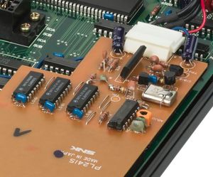
[[File:aes_pll_board.jpg|thumb|First generation AES main clock + PLL board, with bodge-on-a-bodge technology.]] | [[File:aes_pll_board.jpg|thumb|First generation AES main clock + PLL board, with bodge-on-a-bodge technology.]] | ||
It was added during the production of first generation AES consoles as a correction board wired to different locations on the main board. | It was added during the production of [[NEO-AES board|first generation]] AES consoles as a correction board wired to different locations on the main board. | ||
The divider was made using 74LS161 4-bit counters. | The divider was made using 74LS161 4-bit counters. | ||
Latest revision as of 07:42, 7 November 2016
The video PLL circuit is only present in home consoles, it was added as a way to improve composite video quality by adjusting the main clock frequency with the color burst frequency.
Operation

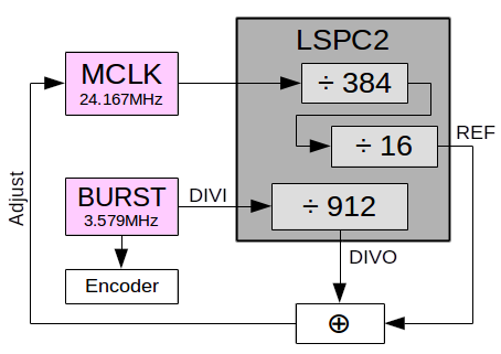
REF is generated by LSPC2-A2from the 24M main clock: Square, 24167829Hz / 384 / 16 = 3933Hz (16 lines)
DIVO is generated by LSPC2 from DIVI (color burst frequency, NTSC 3579545Hz): Not square, DIVO is counter's 10th bit (512 DIVI periods low) and reset at 912 (398 DIVI periods high ?) = 3933Hz also.
DIVO and REF are compared to generate the adjustment voltage for the varicap diode.
DIVI also feeds the video encoder.
First generation

It was added during the production of first generation AES consoles as a correction board wired to different locations on the main board.
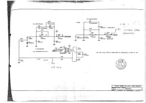
The divider was made using 74LS161 4-bit counters.
Board's reference is PL241S ?
Second generation

When SNK made the second generation chipset, the bodge became part of the system with the inclusion of the divider logic in LSPC2-A2.