Mahjong controller: Difference between revisions
mNo edit summary |
m (Minor rephrasing) |
||
| (One intermediate revision by one other user not shown) | |||
| Line 1: | Line 1: | ||
[[File:Mahjong_controller.jpg|right|thumb|Mahjong controller]] | [[File:Mahjong_controller.jpg|right|thumb|Mahjong controller]] | ||
[[File:Mahjong_IO.png|right|thumb|Mahjong specific I/O test screen (Japan-J3 | [[File:Mahjong_IO.png|right|thumb|Mahjong specific I/O test screen (Japan-J3 system ROM)]] | ||
A special controller designed to play mahjong games. It provides 21 push buttons organized in two rows: | |||
First row | * First row: A B C D E F G H I J K L M N. | ||
* Second row: SELECT START, then PON CHI KAN REACH RON (Japanese: pon chî kan rîchi ron). | |||
=Software= | |||
The mahjong controller is suported by all original [[system ROM]]s. | |||
The MVS system ROM doesn't detect the controller, but reads [[hardware DIPs]] #3 and sets the status byte of INPUT_1 to 3 if set. It never sets INPUT_2 to 3, meaning that the mahjong controller is a single-player setup only on MVS. | |||
The home console system ROM can detect the controller on both ports (by writing 1 to OUT3 and reading the SELECT button) and sets the corresponding input status byte to 3, allowing the use of two mahjong controllers. | |||
Calling [[SYSTEM_IO]] | Calling [[SYSTEM_IO]] reports the controller's status and updates the input data in RAM. | ||
=Hardware= | |||
The controller is built using a multiplexed array of buttons, using the controller port outputs to select which group of buttons to read. OUT3 and SELECT are hardwired to enable detection of the controller by home systems. | |||
OUT3 and SELECT are | |||
The button array is organized as follows: | |||
{|class="wikitable" | |||
{| class="wikitable" | |||
| | | | ||
|align="center"|'''OUT1''' | |align="center"|'''OUT1''' | ||
| Line 67: | Line 65: | ||
|} | |} | ||
SELECT and START are always enabled. | |||
Schematic of the controller: | Schematic of the controller: | ||
Latest revision as of 20:58, 1 April 2017


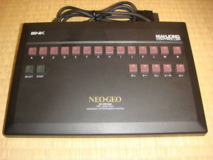
A special controller designed to play mahjong games. It provides 21 push buttons organized in two rows:
- First row: A B C D E F G H I J K L M N.
- Second row: SELECT START, then PON CHI KAN REACH RON (Japanese: pon chî kan rîchi ron).
Software
The mahjong controller is suported by all original system ROMs.
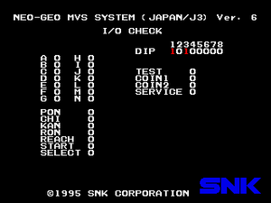
The MVS system ROM doesn't detect the controller, but reads hardware DIPs #3 and sets the status byte of INPUT_1 to 3 if set. It never sets INPUT_2 to 3, meaning that the mahjong controller is a single-player setup only on MVS.
The home console system ROM can detect the controller on both ports (by writing 1 to OUT3 and reading the SELECT button) and sets the corresponding input status byte to 3, allowing the use of two mahjong controllers.
Calling SYSTEM_IO reports the controller's status and updates the input data in RAM.
Hardware
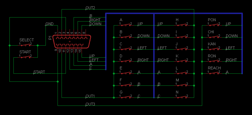
The controller is built using a multiplexed array of buttons, using the controller port outputs to select which group of buttons to read. OUT3 and SELECT are hardwired to enable detection of the controller by home systems.
The button array is organized as follows:
| OUT1 | OUT2 | OUT3 | |
| UP | A | H | PON |
| DOWN | B | I | CHI |
| LEFT | C | J | KAN |
| RIGHT | D | K | RON |
| A | E | L | REACH |
| B | F | M | - |
| C | G | N | - |
SELECT and START are always enabled.
Schematic of the controller:
