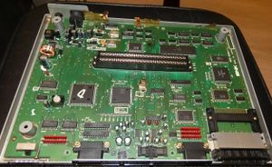
NEO-AES4-1 board: Difference between revisions
Jump to navigation
Jump to search
mNo edit summary |
m (Category) |
||
| (One intermediate revision by the same user not shown) | |||
| Line 1: | Line 1: | ||
[[File:4-1.jpg|thumb|Neo Geo AES 4-1 board]] | |||
Seems to be the sixth and latest board revision. | Seems to be the sixth and latest board revision. | ||
Some (all ?) units appear to be heavily shielded with a metal cover and conductive coating on the plastic shell. | Some (all ?) units appear to be heavily shielded with a metal cover and conductive coating on the plastic shell. | ||
Differences with | =Differences with the [[NEO-AES3-6 board]]= | ||
* The power supply circuit was (finally) moved next to the power connector. | * The power supply circuit was (finally) moved next to the power connector. | ||
| Line 14: | Line 16: | ||
* {{Sig|BNKB|BNKB}}/RBNKB jumper. | * {{Sig|BNKB|BNKB}}/RBNKB jumper. | ||
[[ | [[Category:Cartridge_systems]] | ||
Latest revision as of 11:34, 29 December 2018

Seems to be the sixth and latest board revision.
Some (all ?) units appear to be heavily shielded with a metal cover and conductive coating on the plastic shell.
Differences with the NEO-AES3-6 board
- The power supply circuit was (finally) moved next to the power connector.
- Most through-hole chips were replaced by their surface mount versions.
- The PLCC version of the 68k CPU was used. Also tiny Z80.
- The SP1 ROM is an OTP part.
- Resistor networks were added on bus lines, maybe as an attempt to reduce radiated noise.
- TC9018P composite sync generator.
- SYNC/NEW-SYNC jumper.
- BNKB/RBNKB jumper.