NEO-CDD board: Difference between revisions
Jump to navigation
Jump to search
mNo edit summary |
mNo edit summary |
||
| (3 intermediate revisions by the same user not shown) | |||
| Line 1: | Line 1: | ||
Boards holding the [[Pinouts#Joypad_ports|joypad connectors]], lid and power switch, and configuration jumpers in top-loading [[CD systems]]. | |||
= NEO-CDD3-1 = | =NEO-CDD3-1= | ||
[[File:Neo-cdd3- | [[File:Neo-cdd3-1_schematic.png|300px|thumb|NEO-CDD3-1 schematic]] | ||
The power switch simply connects the yellow "LAND1" wire to ground. | |||
Two {{Chipname|NEO-BUF}} chips are use to switch the 68k data bus appropriately. | |||
All inputs go through [[CRE401]] RC networks. | All inputs go through [[CRE401]] RC networks. | ||
Pin 38 of GA1 (tied to VCC) tells the [[system ROM]] that the system is a top-loader in {{Reg|REG_CDCONFIG}}. | |||
No other versions of this board exist ? | |||
[[File:Neocdd31.jpg]] | |||
[[File:Neocdd31b.jpg]] | |||
[[Category:CD systems]] | [[Category:CD systems]] | ||
[[Category:Chips]] | [[Category:Chips]] | ||
Latest revision as of 19:01, 10 April 2025
Boards holding the joypad connectors, lid and power switch, and configuration jumpers in top-loading CD systems.
NEO-CDD3-1

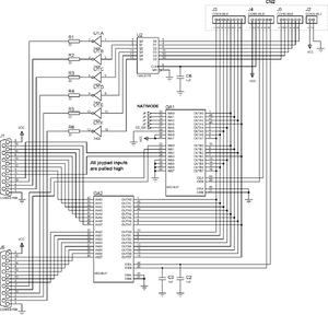
The power switch simply connects the yellow "LAND1" wire to ground.
Two NEO-BUF chips are use to switch the 68k data bus appropriately.
All inputs go through CRE401 RC networks.
Pin 38 of GA1 (tied to VCC) tells the system ROM that the system is a top-loader in REG_CDCONFIG.
No other versions of this board exist ?