MV-LED: Difference between revisions
Jump to navigation
Jump to search
mNo edit summary |
mNo edit summary |
||
| Line 3: | Line 3: | ||
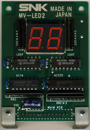
[[File:mv-led2.jpg|thumb|MV-LED2 board, same components, different size. Picture courtesy of [[http://www.mvs-scans.com MVS-Scans]].]] | [[File:mv-led2.jpg|thumb|MV-LED2 board, same components, different size. Picture courtesy of [[http://www.mvs-scans.com MVS-Scans]].]] | ||
LED-based credits display board in original [[MVS hardware|MVS cabs]]. Uses two 7-segment displays to show the player's remaining [[credits]]. | |||
Uses [[CRE401]] | Uses [[CRE401]] arrays for inputs. | ||
Pinout: | Pinout, from left to right (pins 1 to 13): | ||
* | *5V | ||
* | *5V | ||
* | *Clock | ||
*Digit 1 ABCD | *Digit 1 ABCD | ||
*Digit 2 ABCD | *Digit 2 ABCD | ||
| Line 16: | Line 16: | ||
*GND | *GND | ||
Digits are BCD-coded and | Digits are BCD-coded and controlled by registers {{Reg|REG_LEDLATCHES}} and {{Reg|REG_LEDDATA}}. | ||
[[File:74ls47 digits.png|center]] | |||
See also [[MV-ELA]] for the marquee board details. | See also [[MV-ELA]] for the marquee board details. | ||
Revision as of 02:07, 3 March 2016


LED-based credits display board in original MVS cabs. Uses two 7-segment displays to show the player's remaining credits.
Uses CRE401 arrays for inputs.
Pinout, from left to right (pins 1 to 13):
- 5V
- 5V
- Clock
- Digit 1 ABCD
- Digit 2 ABCD
- GND
- GND
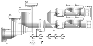
Digits are BCD-coded and controlled by registers REG_LEDLATCHES and REG_LEDDATA.

See also MV-ELA for the marquee board details.

Connection to the MVS board visible in [page 5 of the schematics]