System ROM mapping circuit

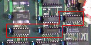
Early boards like the MV4 and MV6 use discrete logic chips instead of NEO-E0 to map in the system ROM (BIOS) when needed.
As these chips are located close to the battery, some systems with leaking batteries may become stuck in watchdog reset.
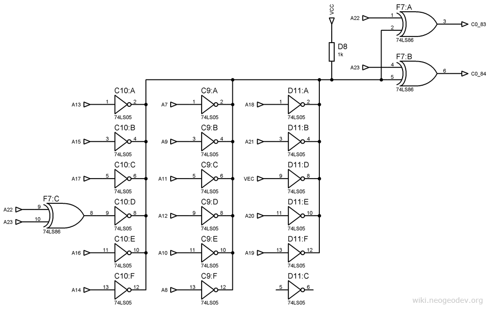
Depending on the board model, chip locations may be different and pins may be swapped but the overall circuit shown below is the same.
Troubleshooting steps:
- 68k address lines A7 to A21 must go to individual inverters in 74LS05 chips.
- All the inverters outputs except one must be connected together to a 1k resistor and two XOR gates inputs (74LS86).
- Those two XOR gates output A22I and A23I, which must go to PRO-C0 pins 83 and 84 respectively.
- One inverter out of all 18 should be unused.
- One inverter must be fed by the VEC signal (74HC259 pin 5).
- One inverter must be fed from the output of a XOR gate (74LS86) having A22 and A23 as inputs.
