MV-ELA: Difference between revisions
mNo edit summary |
mNo edit summary |
||
| (2 intermediate revisions by the same user not shown) | |||
| Line 1: | Line 1: | ||
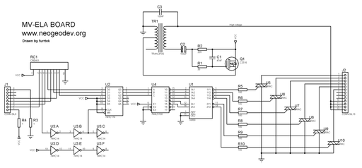
[[File:Mv-ela_schem.png|thumb|512px|MV-ELA schematic]] | [[File:Mv-ela_schem.png|thumb|512px|MV-ELA schematic]] | ||
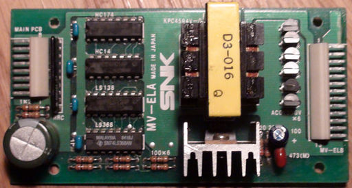
External board provided with original [[MVS hardware|MVS]] cabs to | External board provided with original [[MVS hardware|MVS]] cabs to generate high voltage and switch it to the [[marquee]]'s [[MV-ELC]] or [[MV-ELD]] board(s). | ||
Uses a 5 pin transformer and a C2516 transistor to form a self-oscillating circuit. | Uses a 5 pin transformer and a C2516 transistor to form a self-oscillating step-up circuit. | ||
Uses six 800mA 400V AC0V8 triacs ([http://www.alldatasheet.com/datasheet-pdf/pdf/105128/NEC/AC0V8DGM.html datasheet]) for switching. | Uses six 800mA 400V AC0V8 triacs ([http://www.alldatasheet.com/datasheet-pdf/pdf/105128/NEC/AC0V8DGM.html datasheet]) for switching outputs. | ||
Often produces a high-pitched noise when some panels are lit, this is normal and common with switching PSUs. If the noise is too annoying, | Often produces a high-pitched noise when some panels are lit, this is normal and common with switching PSUs. If the noise is too annoying, replace the transformer. LED mods can also be found. | ||
Software control is done through {{Reg|REG_LEDDATA}}, and {{Reg|REG_LEDLATCHES}} | Software control is done through registers {{Reg|REG_LEDDATA}}, and {{Reg|REG_LEDLATCHES}}. | ||
'''Be careful when manipulating this board when powered: touching the high voltage section can hurt A LOT.''' After disconnecting power, it shouldn't keep a dangerous charge for long (a few seconds). | |||
{| | {| | ||
| Line 15: | Line 17: | ||
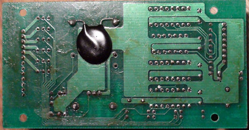
|[[File:Mv-ela_bot.jpg|thumb|512px|MV-ELA bottom, HV cap]] | |[[File:Mv-ela_bot.jpg|thumb|512px|MV-ELA bottom, HV cap]] | ||
|} | |} | ||
=Repair= | |||
The marquee can be tested in the [[system ROM]]'s hardware test menu. The third screen shows an "EL" value which should count from 1 to the number of slots available on the system, turning each panel on in sequence. | |||
If the step-up circuit stalls, the transistor may short 5V to ground. Both resistors near the "MAIN PCB" connector will act as fuses and burn out. | |||
In this case, replace: | |||
* The C2516 transistor | |||
* Both power input resistors (R3 and R4) | |||
* Capacitors and resistors in the feedback circuit (C1, C2, R1 and R2) | |||
* The transformer, if any winding is open | |||
If the step-up circuit works but some or all panels don't light up, check the triacs first, then the logic chips. | |||
[[Category:Cartridge systems]] | [[Category:Cartridge systems]] | ||
[[Category:Repairs]] | [[Category:Repairs]] | ||
Revision as of 08:54, 19 February 2017

External board provided with original MVS cabs to generate high voltage and switch it to the marquee's MV-ELC or MV-ELD board(s).
Uses a 5 pin transformer and a C2516 transistor to form a self-oscillating step-up circuit.
Uses six 800mA 400V AC0V8 triacs (datasheet) for switching outputs.
Often produces a high-pitched noise when some panels are lit, this is normal and common with switching PSUs. If the noise is too annoying, replace the transformer. LED mods can also be found.
Software control is done through registers REG_LEDDATA, and REG_LEDLATCHES.
Be careful when manipulating this board when powered: touching the high voltage section can hurt A LOT. After disconnecting power, it shouldn't keep a dangerous charge for long (a few seconds).
 |
 |
Repair
The marquee can be tested in the system ROM's hardware test menu. The third screen shows an "EL" value which should count from 1 to the number of slots available on the system, turning each panel on in sequence.
If the step-up circuit stalls, the transistor may short 5V to ground. Both resistors near the "MAIN PCB" connector will act as fuses and burn out.
In this case, replace:
- The C2516 transistor
- Both power input resistors (R3 and R4)
- Capacitors and resistors in the feedback circuit (C1, C2, R1 and R2)
- The transformer, if any winding is open
If the step-up circuit works but some or all panels don't light up, check the triacs first, then the logic chips.