MV-LED: Difference between revisions
Jump to navigation
Jump to search
(Created page with "Credits display board in original MVS systems. Uses 2 7-segment displays to show the player's remaining credits. Uses CRE401 RC arrays for inputs. To copy here: htt...") |
mNo edit summary |
||
| (7 intermediate revisions by the same user not shown) | |||
| Line 1: | Line 1: | ||
[[File:mv-led.jpg|thumb|MV-LED board. Picture courtesy of [[http://thearcadeboneyard.com TheArcadeBoneyard]].]] | |||
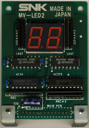
[[File:mv-led2.jpg|thumb|MV-LED2 board, same components, different size. Picture courtesy of [[http://www.mvs-scans.com MVS-Scans]].]] | |||
LED-based credits display board in original [[MVS hardware|MVS cabs]]. Uses two 7-segment displays to show the player's remaining [[credits]]. | |||
Uses [[CRE401]] arrays for inputs. | |||
* | |||
* | Pinout, from left to right (pins 1 to 13): | ||
* | *5V | ||
*5V | |||
*Clock | |||
*Digit 1 ABCD | *Digit 1 ABCD | ||
*Digit 2 ABCD | *Digit 2 ABCD | ||
| Line 14: | Line 16: | ||
*GND | *GND | ||
Digits are BCD-coded and | Digits are BCD-coded and controlled by registers {{Reg|REG_LEDLATCHES}} and {{Reg|REG_LEDDATA}}. | ||
[[File:74ls47 digits.png|center]] | |||
See also [[MV-ELA]] for the marquee board details. | See also [[MV-ELA]] for the marquee board details. | ||
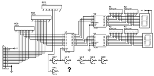
[[Category: | [[File:mv-led2_schem.png|thumb|MV-LED2 board incomplete schematic.]] | ||
Connection to the MVS board visible in [[http://wiki.neogeodev.org/index.php?title=File:Mv1fs-page5.jpg on page 5 of the schematics]] | |||
=Repair= | |||
These boards can be tested in the [[system ROM]]'s hardware test menu. The third screen shows "LED1" and "LED2" values which should change each second. The value shown should be the value displayed on the boards. | |||
[[Category:Repairs]] | |||
[[Category:Cartridge systems]] | [[Category:Cartridge systems]] | ||
Latest revision as of 21:14, 15 August 2017


LED-based credits display board in original MVS cabs. Uses two 7-segment displays to show the player's remaining credits.
Uses CRE401 arrays for inputs.
Pinout, from left to right (pins 1 to 13):
- 5V
- 5V
- Clock
- Digit 1 ABCD
- Digit 2 ABCD
- GND
- GND
Digits are BCD-coded and controlled by registers REG_LEDLATCHES and REG_LEDDATA.

See also MV-ELA for the marquee board details.

Connection to the MVS board visible in [on page 5 of the schematics]
Repair
These boards can be tested in the system ROM's hardware test menu. The third screen shows "LED1" and "LED2" values which should change each second. The value shown should be the value displayed on the boards.