YM3016: Difference between revisions
Jump to navigation
Jump to search
mNo edit summary |
No edit summary |
||
| (6 intermediate revisions by 2 users not shown) | |||
| Line 1: | Line 1: | ||
[[File:aes_ym3016.jpg|thumb|300px|right|YM3016 | [[File:aes_ym3016.jpg|thumb|300px|right|YM3016 found in a AES system.]] | ||
The YM3016 is a floating point, | The YM3016 is a floating point, 16bit stereo Digital-to-Analog Converter (DAC) made to work with the {{Chipname|YM2610}}. | ||
Both chips were made separately to avoid parasitic noise. | Both chips were made separately to avoid parasitic noise. | ||
[[ | Datasheets: [[File:YM3016.pdf]] / [[File:YM3016_jp.pdf]] | ||
=Format= | |||
See US [[SNK Patents|patent]] #5021785 https://www.google.com/patents/US5021785 | |||
=Pinout= | |||
[[File:Ym3016.png]] | |||
[[File:Ym3016.odg]] Todo: TOBUF is an output. | |||
* SD: Serial Data input from YM2610 | |||
* CLK: Serial clock input from YM2610 | |||
* FORM: Format selected (binary or 2's complement), always tied to VCC in NeoGeo systems | |||
* SMP1 & SMP2: Alternating clocks for the L/R sample-and-hold circuits, comes from the YM2610 | |||
* ICL: ? Always tied to VCC | |||
* CH1 & CH2: Left and right audio outputs | |||
* COM: Common input for both sample-and-hold circuits (L/R demux) | |||
* TOBUF: Output to analog buffer for COM | |||
* RB: Bias voltage output ? | |||
[[Category:Chips]] | |||
[[Category:Audio system]] | [[Category:Audio system]] | ||
Latest revision as of 23:52, 19 June 2017

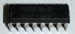
The YM3016 is a floating point, 16bit stereo Digital-to-Analog Converter (DAC) made to work with the YM2610.
Both chips were made separately to avoid parasitic noise.
Datasheets: File:YM3016.pdf / File:YM3016 jp.pdf
Format
See US patent #5021785 https://www.google.com/patents/US5021785
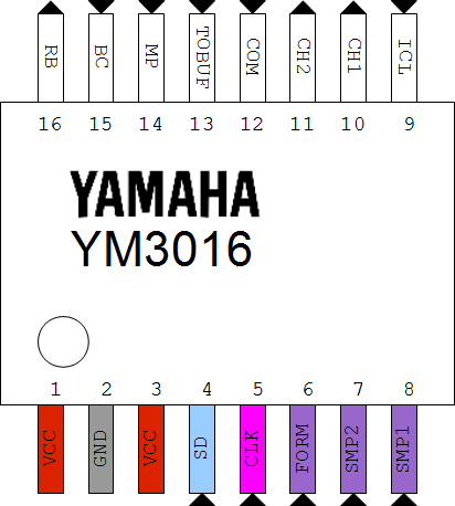
Pinout
File:Ym3016.odg Todo: TOBUF is an output.
- SD: Serial Data input from YM2610
- CLK: Serial clock input from YM2610
- FORM: Format selected (binary or 2's complement), always tied to VCC in NeoGeo systems
- SMP1 & SMP2: Alternating clocks for the L/R sample-and-hold circuits, comes from the YM2610
- ICL: ? Always tied to VCC
- CH1 & CH2: Left and right audio outputs
- COM: Common input for both sample-and-hold circuits (L/R demux)
- TOBUF: Output to analog buffer for COM
- RB: Bias voltage output ?
