Clock: Difference between revisions
Jump to navigation
Jump to search
mNo edit summary |
mNo edit summary |
||
| Line 5: | Line 5: | ||
The main system clock (sometimes called '''mclk''') is 24MHz. It is generated and divided by 2, 4 and 24 by {{Chipname|NEO-D0}} to provide the 12MHz clock for {{Chipname|NEO-ZMC2}}, the inverted 6MHz one for [[video DAC|video output]] and also the 1MHz one for {{Chipname|NEO-B1}}. | The main system clock (sometimes called '''mclk''') is 24MHz. It is generated and divided by 2, 4 and 24 by {{Chipname|NEO-D0}} to provide the 12MHz clock for {{Chipname|NEO-ZMC2}}, the inverted 6MHz one for [[video DAC|video output]] and also the 1MHz one for {{Chipname|NEO-B1}}. | ||
{{Chipname|LSPC2-A2}} divides it by 3 and 6 to provide the 8MHz clock for the {{Chipname|YM2610}} and the 4MHz one for the {{Chipname|Z80}}. | |||
The cartridge connector provides the {{Sig|24M|24M}}, 12MHz, 8MHz and 4MHz inverted clock signals. | The cartridge connector provides the {{Sig|24M|24M}}, 12MHz, 8MHz and 4MHz inverted clock signals. | ||
Revision as of 13:05, 28 February 2016
In cartridge systems
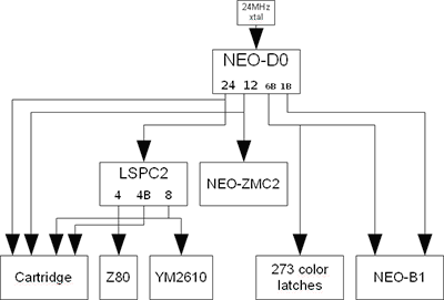
The main system clock (sometimes called mclk) is 24MHz. It is generated and divided by 2, 4 and 24 by NEO-D0 to provide the 12MHz clock for NEO-ZMC2, the inverted 6MHz one for video output and also the 1MHz one for NEO-B1.
LSPC2-A2 divides it by 3 and 6 to provide the 8MHz clock for the YM2610 and the 4MHz one for the Z80.
The cartridge connector provides the 24M, 12MHz, 8MHz and 4MHz inverted clock signals.
A second quartz is used for generating the color burst needed by composite video, for the video encoders.
 "B" signals are phase-inverted.
In CD systems
NEO-GRC ?