Clock: Difference between revisions
mNo edit summary |
mNo edit summary |
||
| Line 1: | Line 1: | ||
Not to be confused with the [[RTC|real time clock]] (RTC), which is clocked independently. | |||
[[File:Clkdistribution.png|frame]] | [[File:Clkdistribution.png|frame]] | ||
=In cartridge systems= | |||
The main system clock ( | The main system clock (often called '''mclk''') is either 24MHz (MVS) or 24.167829MHz (AES). It is generated and divided by 2, 4 and 24 by {{Chipname|NEO-D0}} from a crystal oscillator, to provide the 12MHz clock for {{Chipname|NEO-ZMC2}}, the inverted 6MHz one for [[video DAC|video output]] and also the 1MHz one for {{Chipname|NEO-B1}}. | ||
{{Chipname|LSPC2-A2}} divides it by 3 and 6 to provide the 8MHz clock for the {{Chipname|YM2610}} and the 4MHz one for the {{Chipname|Z80}}. | {{Chipname|LSPC2-A2}} divides it by 3 and 6 to provide the 8MHz clock for the {{Chipname|YM2610}} and the 4MHz one for the {{Chipname|Z80}}. | ||
| Line 9: | Line 11: | ||
The cartridge connector provides the {{Sig|24M|24M}}, 12MHz, 8MHz and 4MHz inverted clock signals. | The cartridge connector provides the {{Sig|24M|24M}}, 12MHz, 8MHz and 4MHz inverted clock signals. | ||
A second quartz is used for generating the color burst needed by composite video, for the [[video encoder]]s. | A second quartz oscillator is used for generating the color burst needed by composite video, for the [[video encoder]]s. | ||
A third 32768Hz quartz oscillator is used for the RTC. | |||
[[File:clock.png]] | [[File:clock.png]] | ||
"B" signals are phase-inverted. | "B" signals are phase-inverted. | ||
== In CD systems | ==Signals== | ||
* {{Sig|24M|24M}} | |||
* {{Sig|12M|12M}} | |||
* {{Sig|68KCLK|68KCLK}} : 12MHz | |||
* {{Sig|68KCLKB|68KCLKB}} : 12MHz | |||
* {{Sig|8M|8M}} | |||
* {{Sig|6MB|8MB}} | |||
* {{Sig|4M|4M}} | |||
* {{Sig|4MB|4MB}} | |||
* {{Sig|1MB|1MB}} : Really 3MHz ? | |||
=In CD systems= | |||
[[File:Cd2_quartz.jpg|thumb|System clock and color burst generation circuit on a CDM3-2 board.]] | [[File:Cd2_quartz.jpg|thumb|System clock and color burst generation circuit on a CDM3-2 board.]] | ||
{{Chipname|NEO-GRC}} ? | |||
[[Category:Base system]] | [[Category:Base system]] | ||
Revision as of 11:47, 5 March 2016
Not to be confused with the real time clock (RTC), which is clocked independently.
In cartridge systems
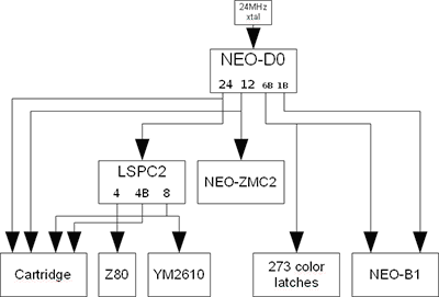
The main system clock (often called mclk) is either 24MHz (MVS) or 24.167829MHz (AES). It is generated and divided by 2, 4 and 24 by NEO-D0 from a crystal oscillator, to provide the 12MHz clock for NEO-ZMC2, the inverted 6MHz one for video output and also the 1MHz one for NEO-B1.
LSPC2-A2 divides it by 3 and 6 to provide the 8MHz clock for the YM2610 and the 4MHz one for the Z80.
The cartridge connector provides the 24M, 12MHz, 8MHz and 4MHz inverted clock signals.
A second quartz oscillator is used for generating the color burst needed by composite video, for the video encoders.
A third 32768Hz quartz oscillator is used for the RTC.
"B" signals are phase-inverted.
Signals
In CD systems
NEO-GRC ?
