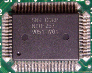
NEO-257

| |
| Package | QFP64R |
| Manufacturer | |
| First use | 1990 ? |
| Used on | MV2B... |
Four "74HC257" quad 2-to-1 multiplexers with some common select lines and output enables. Makes 16 switches in one chip (32 inputs, 16 outputs).
Used in dual slot MVS systems to switch between carts.
Select signal comes from one of the "SLOT" outputs of NEO-F0 ?
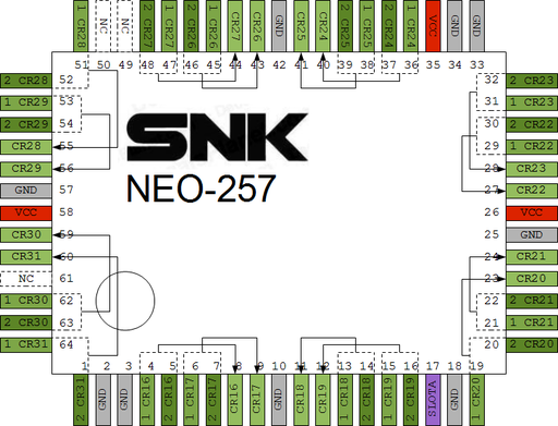
MV2B @ L4 pinout
Used to switch the upper 16 bits of the sprite graphics bus.
OpenOffice Draw file: File:Neo-257 L4.odg
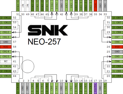
MV2B @ K4 pinout
Used to switch the lower 16 bits of the sprite graphics bus.
OpenOffice Draw file: File:Neo-257 K4.odg
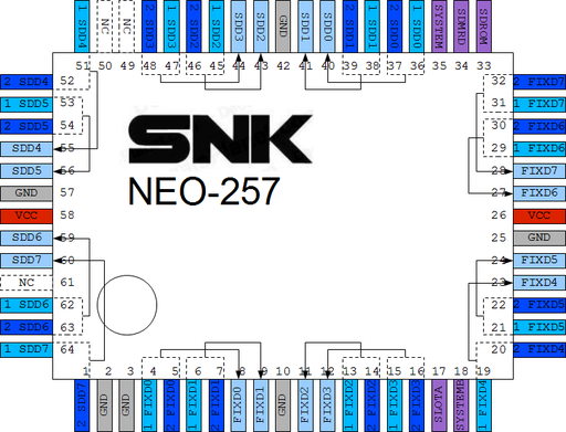
MV2B @ J11 pinout
Used to switch between the onboard SM1 ROM / game M1 ROM, and onboard SFIX ROM / game S ROM.
OpenOffice Draw file: File:Neo-257 J11.odg
Pinout
Information provided by Channelmaniac.
OpenOffice Draw file: File:Neo-257.odg
- A*,B*: Inputs
- Y*: Outputs
- Select: Output A if LOW, B if HIGH.
- Some pins marked as ground could be "enable" pins
- 35 is active high enable for entire chip
- 18 is active low enable for Y0~Y7 (comes from "SYSTEMB" on a MV-2F and used to control /OE for FIXD0~FIXD7 from cart)
- 33 is active low enable for Y8~Y15 (comes from "SDROM" from NEO-D0 to output cart M1 data to Z80)


