NEO-FTC1B board: Difference between revisions
Jump to navigation
Jump to search
mNo edit summary |
m (→Inputs) |
||
| (One intermediate revision by the same user not shown) | |||
| Line 1: | Line 1: | ||
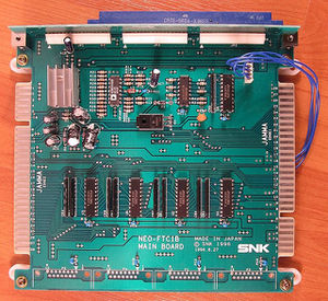
[[File:Ftc1b.jpg|thumb|Picture courtesy of [[http://www.mvs-scans.com MVS-Scans]].]] | [[File:Ftc1b.jpg|thumb|Picture courtesy of [[http://www.mvs-scans.com MVS-Scans]]. EDGE1 is on the right, EDGE2 on the left.]] | ||
[[Multiplayer]] [[extension board]] | [[Multiplayer]] [[extension board]] used with [[Kizuna Encounter - Super Tag Battle]] to allow 4 players to play on the same system. It forms a Y splitter with 2 [[JAMMA connector pinout|JAMMA]] edges to connect two displays, two pair of speakers and two sets of 2-player controls. | ||
It multiplexes the inputs | It multiplexes the inputs by using selection signals coming from a 4-wire (actually 2 used) cable that connects to the [[output port]] of the {{PCB|MV1B}} or {{PCB|MV1C}}, it also provides video signal buffering and power for the speakers ([[power amp]] under the heatsink). | ||
=Inputs= | =Inputs= | ||
The {{Reg|REG_POUTPUT}} register is used to detect the board and select which set of inputs to read. | |||
* OUT1: set selection | |||
* OUT2: seems unused | |||
* OUT3: used for board detection by some versions of the [[system ROM]] | |||
{|class="wikitable" | |||
!OUT1||P1 reads||P2 reads | |||
|- | |||
|low||EDGE 1 P1||EDGE 2 P1 | |||
|- | |||
|high||EDGE 1 P2||EDGE 2 P2 | |||
|} | |||
When OUT3 is high, it simulates presses on particular buttons: | |||
* | * EDGE 1 player 1 button A | ||
* | * EDGE 2 player 1 button A | ||
* EDGE 1 player 2 button B | |||
* EDGE 2 player 2 button B | |||
=Schematic= | |||
= | |||
[[File:Ftc1b_schematic.png|800px]] | [[File:Ftc1b_schematic.png|800px]] | ||
Latest revision as of 20:36, 19 September 2025

Multiplayer extension board used with Kizuna Encounter - Super Tag Battle to allow 4 players to play on the same system. It forms a Y splitter with 2 JAMMA edges to connect two displays, two pair of speakers and two sets of 2-player controls.
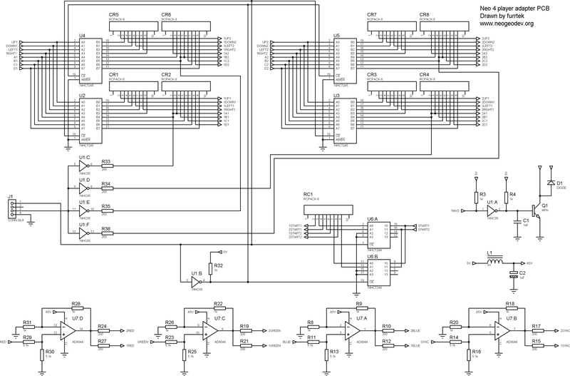
It multiplexes the inputs by using selection signals coming from a 4-wire (actually 2 used) cable that connects to the output port of the MV1B or MV1C, it also provides video signal buffering and power for the speakers (power amp under the heatsink).
Inputs
The REG_POUTPUT register is used to detect the board and select which set of inputs to read.
- OUT1: set selection
- OUT2: seems unused
- OUT3: used for board detection by some versions of the system ROM
| OUT1 | P1 reads | P2 reads |
|---|---|---|
| low | EDGE 1 P1 | EDGE 2 P1 |
| high | EDGE 1 P2 | EDGE 2 P2 |
When OUT3 is high, it simulates presses on particular buttons:
- EDGE 1 player 1 button A
- EDGE 2 player 1 button A
- EDGE 1 player 2 button B
- EDGE 2 player 2 button B
